Starter motor:
the field coils consist of soft iron pole shoes with heavy conductors wound around them.
*current flows through the windings to produce a magnetic field. the pole shoes indensity the strengh of the magnetic field.
*the armature is a group of conductors that are mounted around an iron core in a cyclindrical manner and are supported on a central pivot.
*brushes: supply the postive (battery) supply and the negative (earth) to the conductor.
*starter drives "the pinion gear is driven by the armature." & "the ring gear is attached to the flywheel of the engine."
* one way clutch a.--"the purposes of the one way clutch are"
1. to allow the starter motor to turn the engine.
2. to prevent the engine turning the starter motor. "if the pinion is driven in the direction of the arrow, the one way clutch will release allowing the pinion."
STARTER TYPES ARE THREE "with light vehicles only." there are some other starter motors but for the heavy duties like bulldozer.
1. INERTIA.
2. PRE-ENGAGED.
3. GEAR REDUCTION.
1) INERTIA
Magnetic-torque Production
When the current flows through the yoke field windings, it converts the yoke into an electromagnet due to which a magnetic field or flux is created between the pole-pieces (Fig. 15.15). Similarly, due to the flow of current through the armature loop, concentric rings of magnetic flux are established around the two half-conductor cores. This magnetic flux flows anticlockwise around the left-hand conductor and clockwise around the right-hand conductor.
It can be seen from the figure that the magnetic lines of force between the yoke poles and those for the armature conductors travel in the same direction, and the two sets of lines merge and strengthen each other. This is indicated below the left-hand conductor and above the right-hand conductor. Conversely, where the yoke and armature magnetic fields travel in opposite directions, they neutralise each other. Hence, the field strength above the left-hand conductor and below the right-hand conductor is very weak. The difference in the magnetic field strengths above and below each conductor gives rise to a net upward force, exerted on the left-hand conductor and a net downward force, on the right-hand conductor so that a clockwise-rotating torque is applied to the armature loop.
 Fig. 15.15. Production of a magnetic torque.
 Fig. 15.16. Inertia starter motor.
Commutation
When battery supplies power to the armature loop, the magnetic-field interaction rotates the loop causing the two half-conductors to change places with each other. Also this alters the direction of the current flowing in the conductor relative to the North and South Poles of the yoke. As a result the loop reverses its direction of rotation and turns backward.
To have the continuous rotation of armature loop in only one direction, the direction of current flowing in each half-loop is required to be reversed every half-revolution, called commutation. This is achieved by connecting the armature-loop ends to a split-ring (Fig. 15.14). As a result each half-ring segment comes in contact with a different brush during every half revolution of the armature, so that the direction of the current flow within the armature loop repeatedly reverses.
 Fig. 15.17. Starter-motor commutators and brush-gear.
A. Face commutator brush-gear. B. Axial or face commutator.
C. Radial commutator brush-gear. D. Radial or barrel commutator.
15.4.3.
2) PRE-ENGAGED
Fig. 15.17. Starter-motor commutators and brush-gear.
A. Face commutator brush-gear. B. Axial or face commutator.
C. Radial commutator brush-gear. D. Radial or barrel commutator.
15.4.3.
2) PRE-ENGAGED
 Permanent-magnet Starter Motor
Permanent magnet starters were introduced on the vehicles in the late 1980s. Less weight and small size are the two advantages of these motors, compared to conventional types. This causes the permanent magnet starter to be more popular as less space is available for engine electrical in modern cars. The reduction in weight also contributes towards reduction in fuel consumption. The standard permanent magnet starters produced are suitable for spark ignition engines up to about 2L capacity and are rated in the capacity of 1 kW or less. Some examples are the Bosch DM range (Fig. 15.23) and the Lucas Models M78R / M80R (Fig. 15.24)
 Fig. 15.23. Bosch permanent magnet starter.
 Fig. 15.24. Lucas M78R I M80R starter.
The principle of operation is almost similar to the conventional pre-engaged starter motor, in which the field windings and pole shoes are replaced with high quality permanent magnets. This provides a reduction in weight up to 15 percent. The diameter of the yoke can also be reduced by a similar value. Permanent magnets provide constant excitation due to which the
speed and torque characteristic is expected to be constant. However, due to the fall in battery voltage under load and the low resistance of the armature windings, the characteristic is comparable to that of series wound motors. Sometimes flux concentrating pieces or inter-poles are installed between the main magnets (Fig. 15.25). The warping effect of the magnetic field causes the characteristic curve to be very similar to that of the series motor.
Considerable improvement in the construction of the brushes has taken place. A copper and graphite mix is used to make the brushes in two parts, so that higher copper content is in the power zone and higher graphite content is in the commutation zone. This provides an increase in the service life and a reduction in voltage drop, giving higher starter power output.
Permanent magnet motors for a higher power application, have been developed with intermediate transmission of generally epicyclic type (Fig. 15.26). These enable the armatures to rotate at a higher and more efficient speed while delivering the torque, due to the gear reduction. Permanent magnet starters with intermediate transmission are available with power outputs of about 1.7 kW, suitable for spark ignition engines up to about 5 L or compression ignition engines up to about 1.6 L. The principle of operations of this type of permanent magnet motor is again similar to the conventional pre-engaged starter, but can provide a weight saving of up to 40 percent.
 Fig. 15.25. Permanent magnet fields with inter-poles.
 Fig. 15.26. Starter motor intermediate transmission.
In the epicyclic type intermediate transmission, the sun gear is on the armature shaft and the pinion is driven by the planet carrier. The ring gear or annulus remains stationary acting as an intermediate bearing. This arrangement of gears provides a reduction ratio of about 5:1, which can be calculated by the simple formula;
Reduction Ratio = (A + S)/S
where, A = number of teeth on the annulus
S – number of teeth on the sun gear.
3) GEAR REDUCTION
 Construction
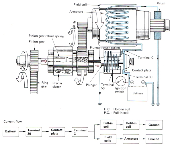
This type of starter motor contains a magnetic switch, A compact high-speed motor, Several reduction gears, A pinion gear, A starter clutch etc. The extra gears reduce the motor speed by a factor of one to three or four and transmit it to the pinion gear. The plunger of the magnetic switch directly pushes the pinion gear, Which is located on the same axis, Causing it to mesh with the ring gear. This type of starter motor generates much greater torque, In proportion to size and weight, Than the conventional type.
 Operation
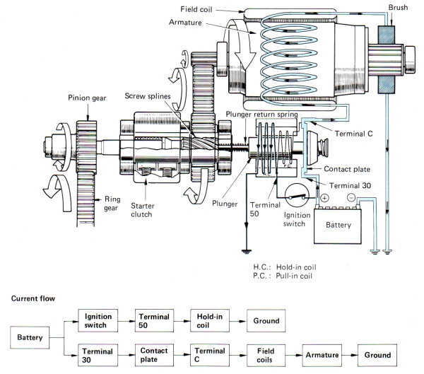
- 1. Ignition Switch In START Position
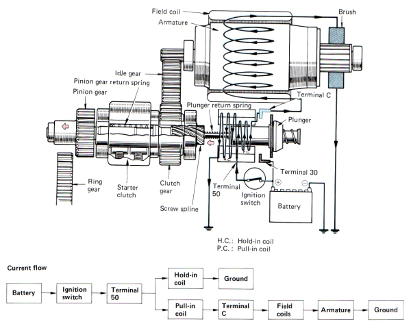
When the ignition switch has been turned to the START position, Terminal 50 passes electrical current from the battery to the hold-in and pull-in coils. From the pull-in coil, The current then flows to the field coils and armature coils via Terminal C. The motor rotates at a lower speed at this point, Since the energized pull-in coil causes a voltage drop which limits the supply of current to the motor components (The field coils and the armature). The hold-in and pull-in coils, At the same time, Set up a magnetic field which pushes the plunger to the left against the return springs. The pinion gear therefore shifts to the left until it engages with the ring gear. The low motor speed at this stage means that both gears mesh smoothly. The screw splines also help the pinion and ring gears to engage more smoothly.
- 2. Pinion And Ring Gears Engaged
When the magnetic switch and the screw splines have pushed the pinion gear to the position where it meshes completely with the ring gear, The contact plate attached to the plunger turns the main switch on by short-circuiting the connection between terminals 30 and C. The resulting connection allows the larger electrical current to pass through the starter motor, Which causes the motor to rotate with a greater torque. The screw splines help the pinion gear mesh more securely with the ring gear. At the same time, The voltage levels at both ends of the pull-in coil become equal so that no current flows through this coil. The plunger is therefore held in position by the magnetic force exerted by the hold-in coil.
- 3. Ignition Switch In ON Position
Turning the ignition switch back to the ON position from START cuts off the voltage being applied to terminal 50. The main switch remains closed, However, Some current flows from Terminal C to the hold-in coil via the pull-in coil. Since current flows through the hold-in coil in the same direction as when the ignition switch is in the START position, It generates a magnetic force which pulls the plunger. In the pull-in coil on the other hand, Current flows in the opposite direction, Generating a magnetic force which attempts to return the plunger to its original position. The magnetic fields set up by these two coils cancel each other out, So the plunger is pulled backward by the return springs. Therefore, The heavy current which has been supplied to the motor is cut off and the plunger disengages the pinion and ring gears at about the same time. The armature used in the reduction type starter motor has less inertia than the one in the conventional type, So friction soon brings it to a stop. This type of starter motor therefore does not require the brake mechanism used in the conventional type starter motor.